Things that did not go as planned, things that should be done different and other unexpected stuff.
General
Essential tools and stuff to start the build that is not mentioned in the manual (at least I did not see it):
- 2 x #21 Countersink Cutter – 120° to countersink the main spar
- #40, #30, Countersink Cutters 120°
- Microstop Countersink Tool to create consistent countersinks
- DRDT-2 from http://experimentalaero.com/ for the dimpling process
- Reamers for M4 rivnuts, 3.2mm and 4.1mm rivets
- and other tools listed on my Amazon shopping list
- The Milwaukee M12 Rivet Gun
- Steel rulers for deburring edges (tip from Evan)
- The Garmin GAP-26 pitot tube comes without srews. Those #6-32 screws are the same that hold the old 3.5″ hard disks in your PC. So you might have some.
Rivnuts
Loctite has almost no effect on the force to spin a rivnut, where super glue at least doubles the force you need to spin the rivnut. I recommend using super glue instead of Loctite to secure rivnuts. More insights in this Kitplanes article.
Engine
The throttle cable has really only one way to be routed from the engine to the throttle lever. When mounting the throttle cable on the engine and performing a test fit with the center console installed, it was observed that the cable was too short. Therefore, it is advisable to verify the cable length while the center console is in place to ensure proper fit and function.
Fuselage
Addressing Plastic Bushings Binding Issues
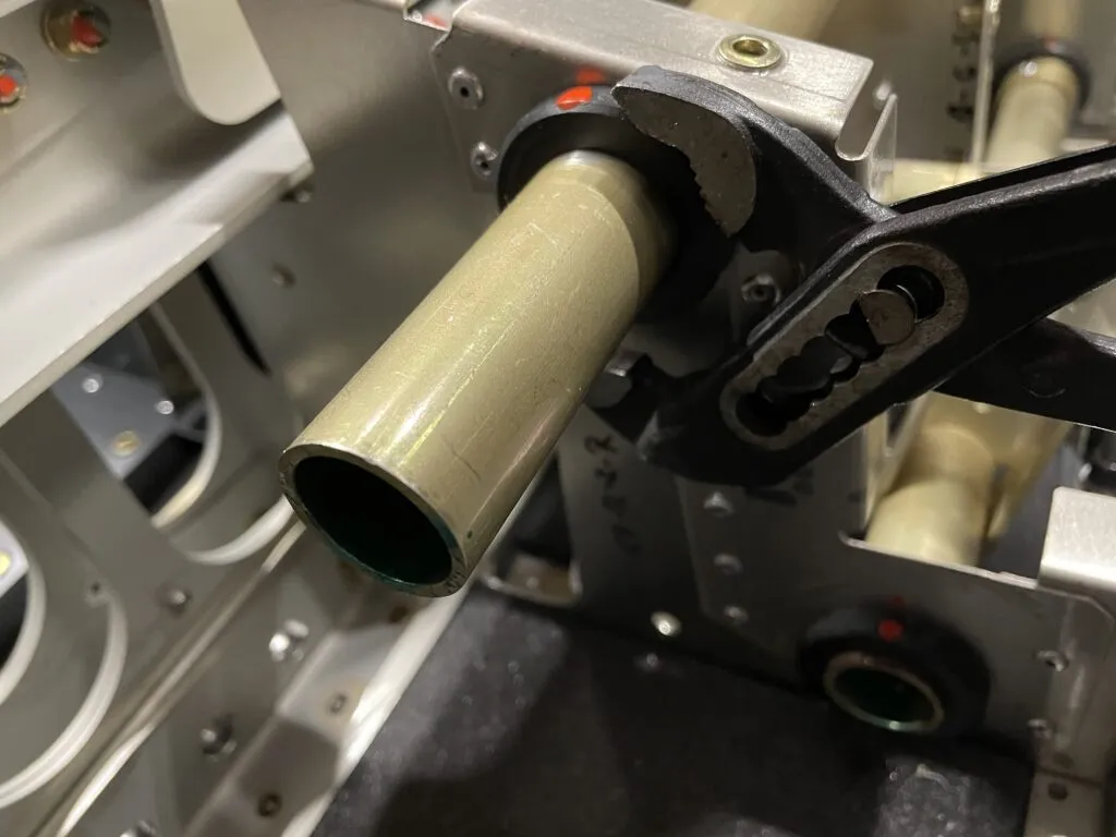
When using the plastic bushings provided with control tubes, they should easily fit onto the tubes. However, binding issues might arise after riveting the brackets that secure the bushings. To prevent this, carefully remove material from the brackets until the bushings fit without any pressure applied. Be cautious not to remove excessive material.
If binding occurs post-riveting, mark the top position of the bushing and use pliers to gently move it back and forth several times, while keeping the top position aligned. Rotate the bushing no more than 90 degrees during this process. This will allow the bracket to gradually cut into the bushing from the outside, where the pressure is highest, effectively resolving the binding issue.
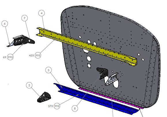
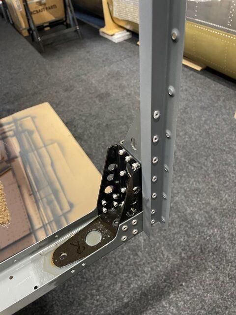
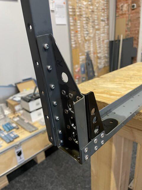
Firewall Mounting Channel
It’s much easier to assemble the upper firewall bracket together with the side skin channels before mounting any of those parts to the side skins or firewall. The steel parts (Top Steel Brackets) seem to have more tolerances and are sometimes not easy to fit to the other aluminum parts.
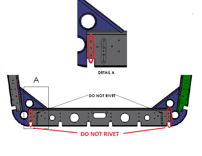
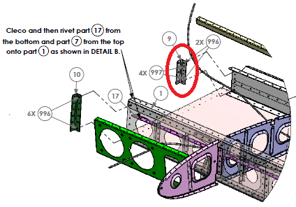
RIB-2 Assembly: Don’t rivet the six holes marked in red as shown in the plans (Jan. 2021). This is where the ribs from the center fuselage connect to the rear fuselage.
WINGs
- Ailerons: The KAI-002-X-F-5 shows for the assembly of rib 4 to use (997) 3.2 x 8mm countersunk rivets to rivet the AN4 anchor nut. They won’t fit and you have to use 2.4 x 6mm stainless steel countersunk rivets, which are supplied with the kit.
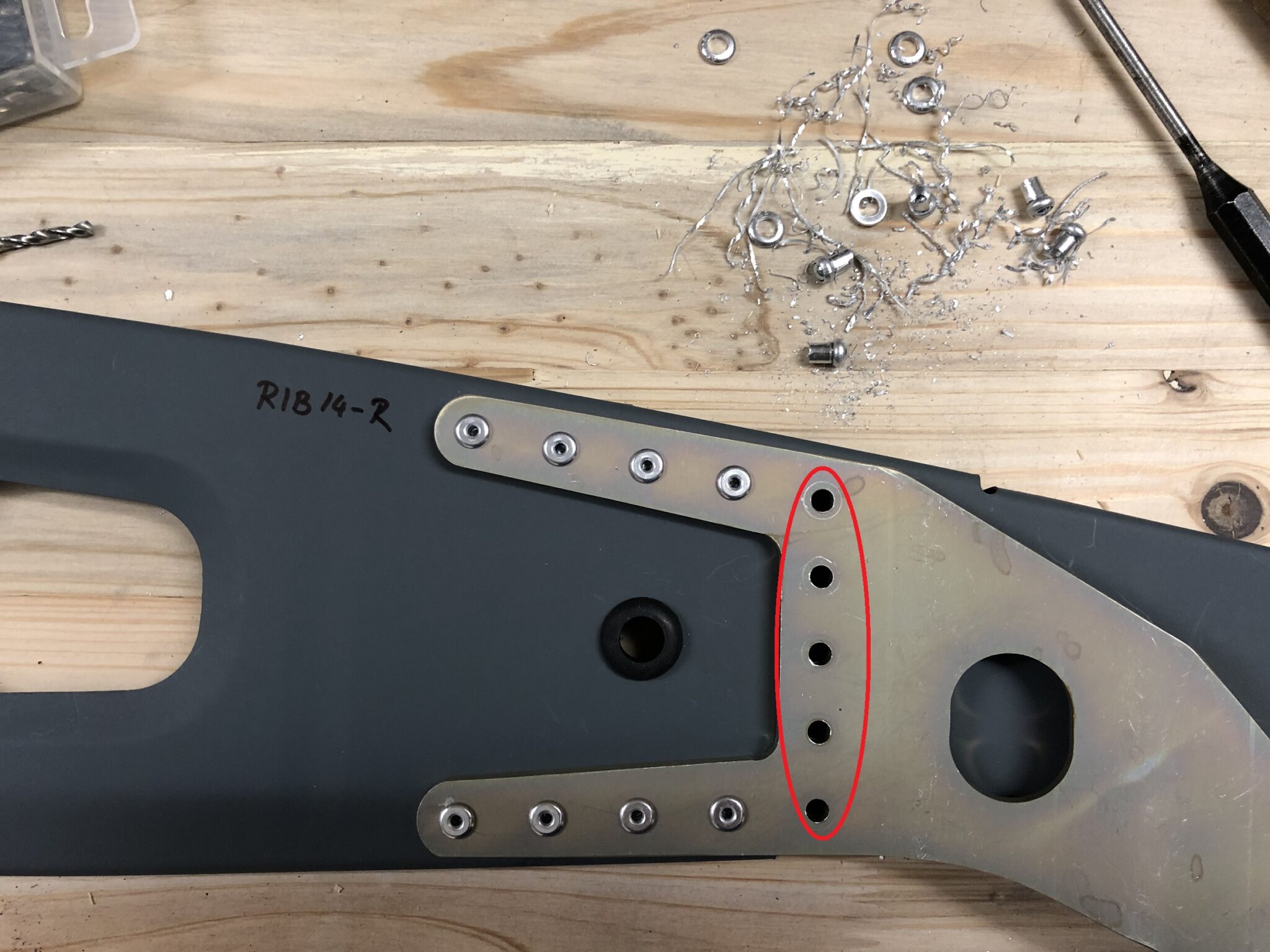
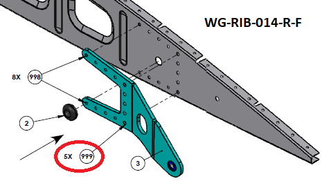
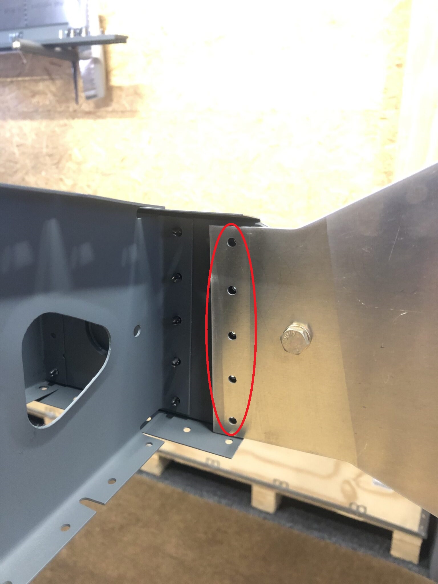
- Do not rivet these holes in wing RIB-14 as shown by the plan. You need to rivet RIB-14 to the “Rear Spar Rib S14 Angle” to connect it to the rear spar here.
- The eybolts for the pushrods inside the wings are in the “Finishing Kit”.
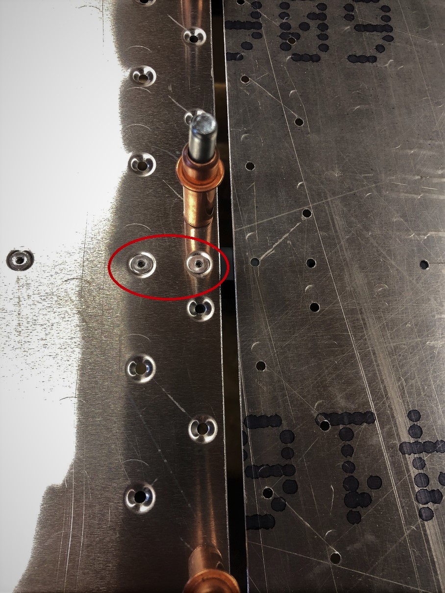
- Do not rivet these two rivets on the bottom skin when mounting the “Lower Wing Stringer”. The bottom root skin will overlap here. You could see it on the plan, but I did not.
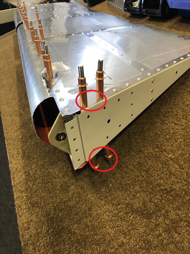
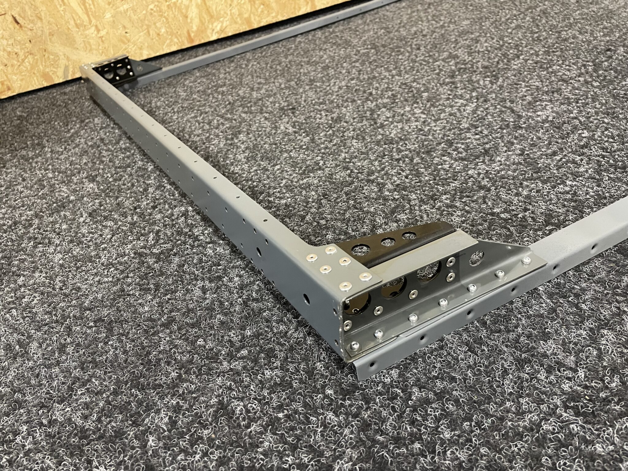
- I would rivet the last row of rivets on the rear spar later. These holes should be used to attach the rear spar to the wing jig.
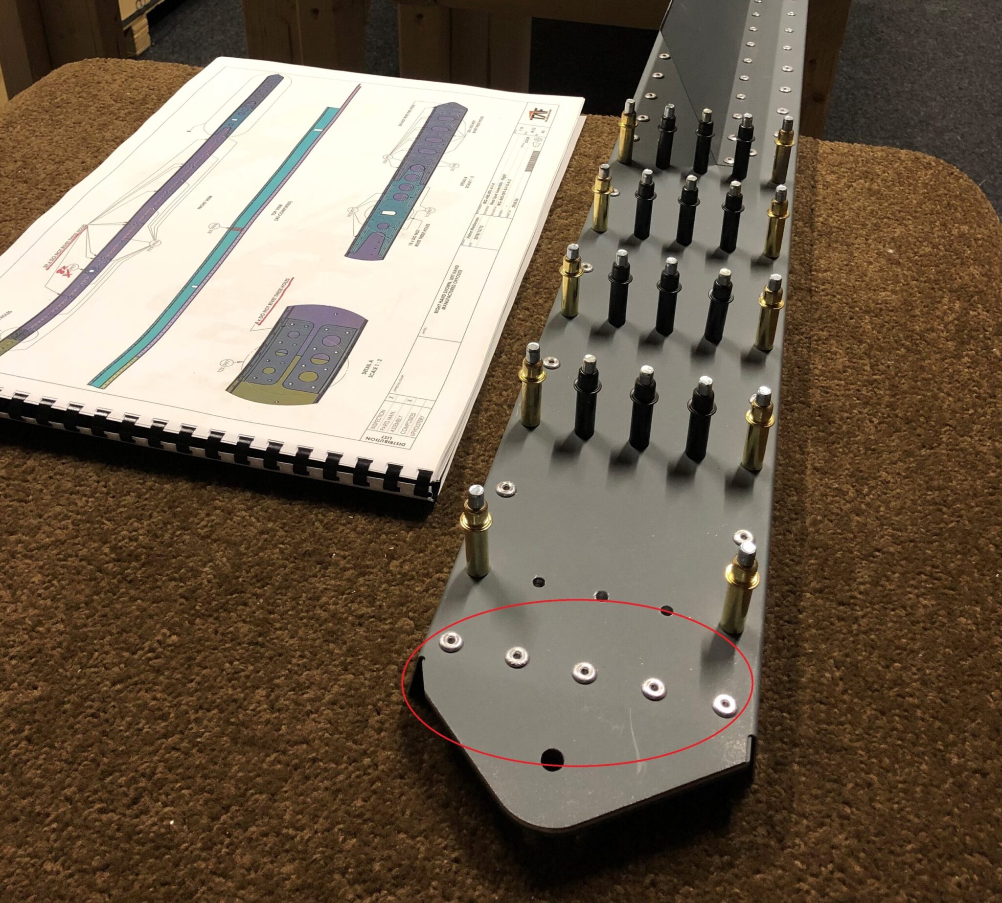
- The “rear spar upper skin support channel” should be riveted to the rear spar “after” the rear spar has been riveted to the wing ribs. As you see on the picture, the lower two holes can’t be reached with a rivet gun.
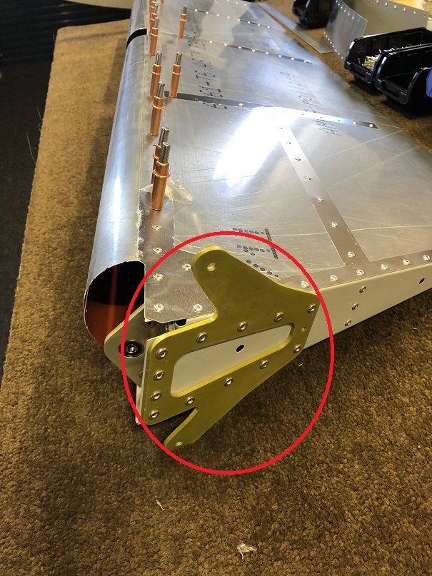
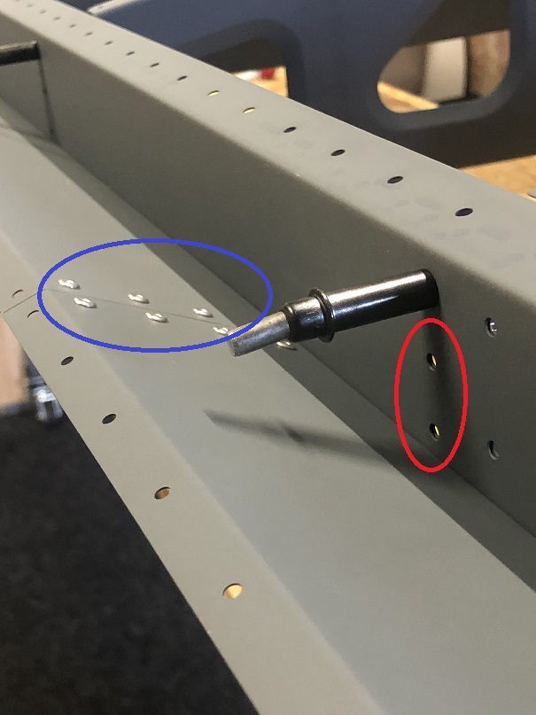
- The rivets in the blue circle (holding the WG-PLT-005-X-F-0 Rear Spar Upper Skin Support Plate, (10) on page W2.1) should be riveted from the other side (not as shown in the picture), because the rivet ends interfere with the flaps movement.
Rudder
The 4 skin rivets next to the “Rudder Control Bracket” (12) are hard to rivet, when the rudder control bracket is installed. So I omitted “Step 6” in the KAI and installed the bracket after riveting the skin. I would also recommend installing the “Rudder Counterbalance Weight” (2) after putting the rudder skin (14) on instead of doing it in “Step 2”. The “Rudder Counterbalance Weight” adds a lot of weight to a flimsy structure.