 by
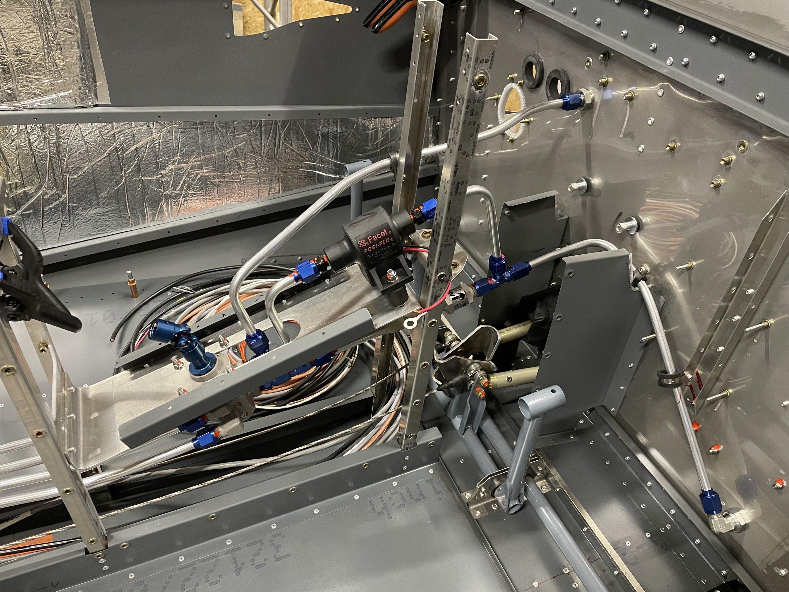
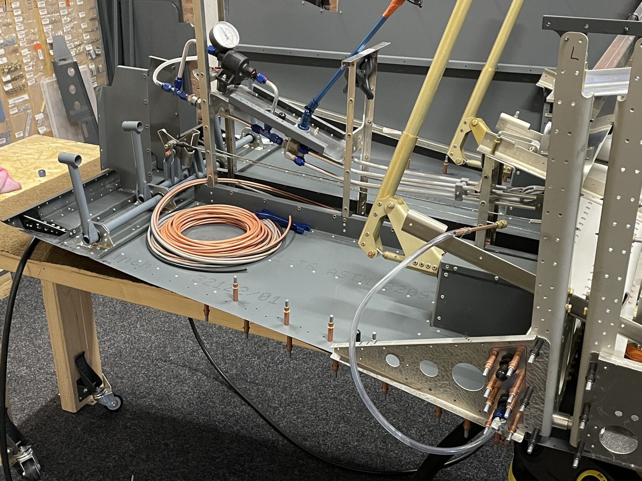
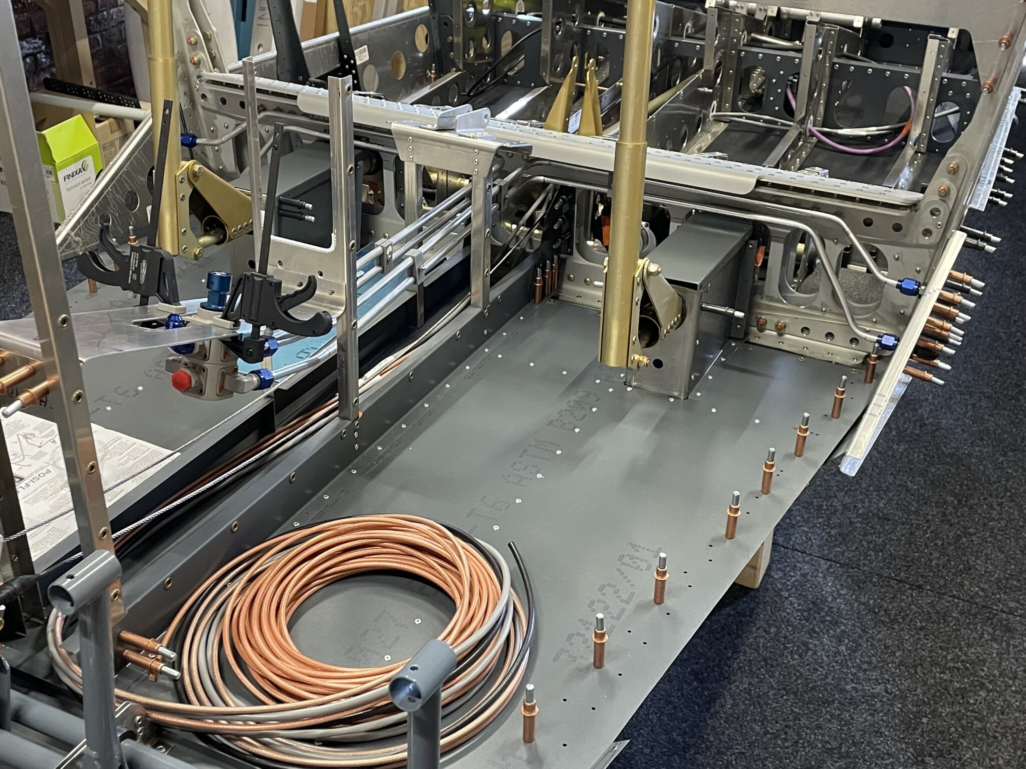
by Based on recommendations from other builders, I decided to use 3/8-inch aluminum fuel lines inside the fuselage instead of the provided rubber fuel hoses, which need to be replaced every 5 years. This task can be messy and unpleasant, and it’s best to install the fuel lines while working on the center fuselage. Otherwise, it might be challenging to insert them later due to limited space in the center channel and the need for precise positioning of the fuel valve connection. To make installation easier, I ordered an extension kit from Andair, which I can cut to the needed length when I mount the center console.
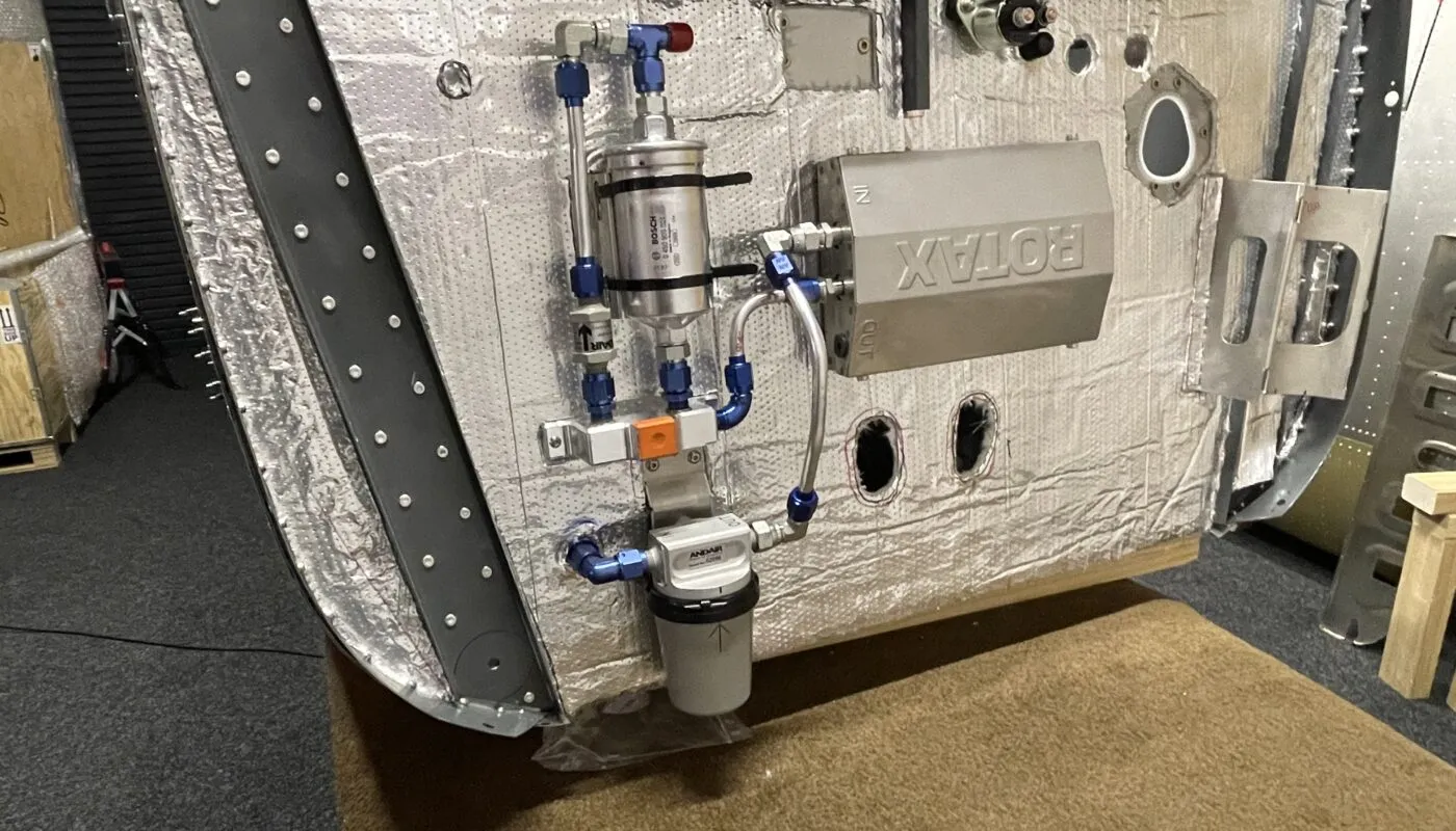
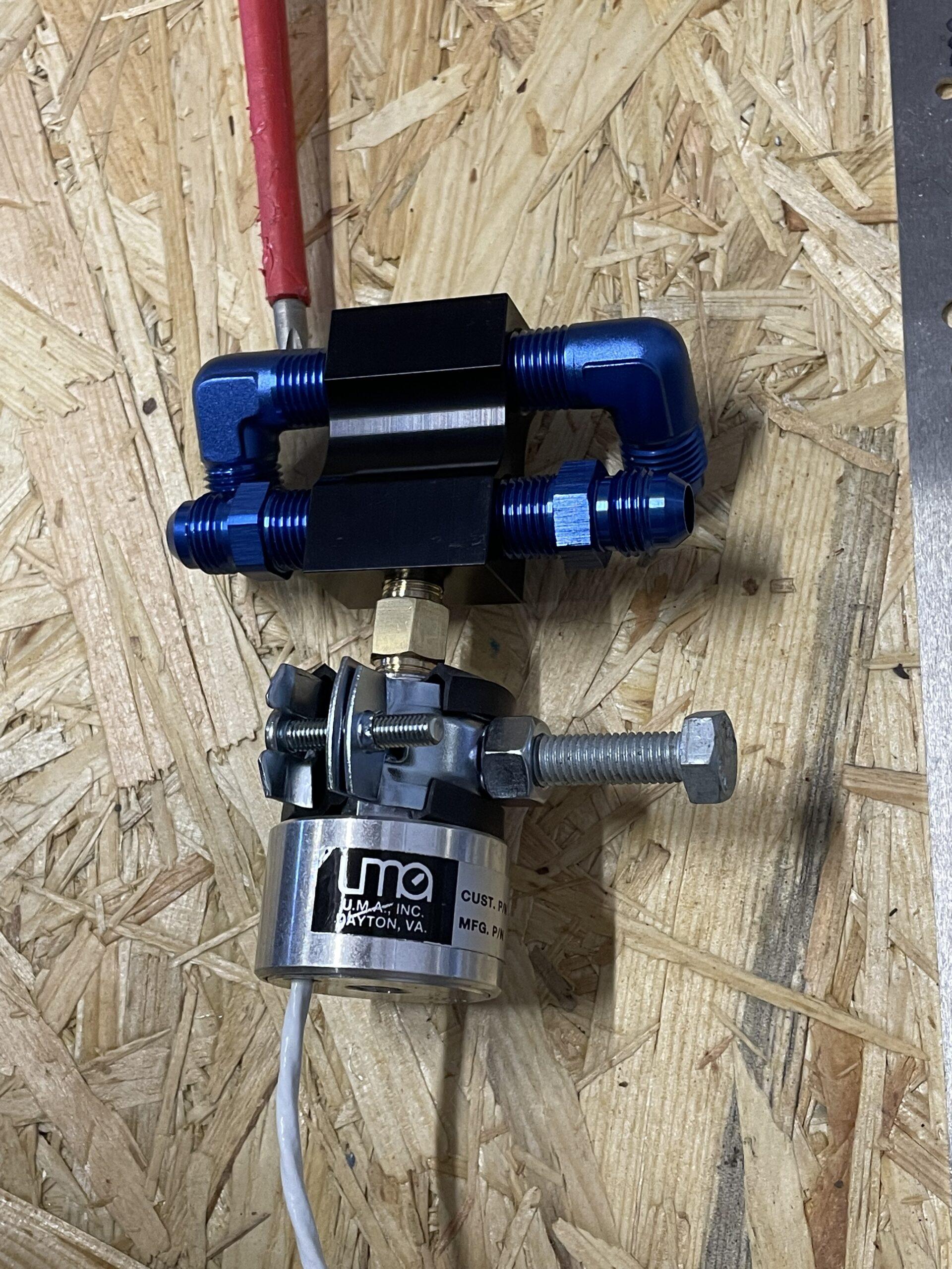
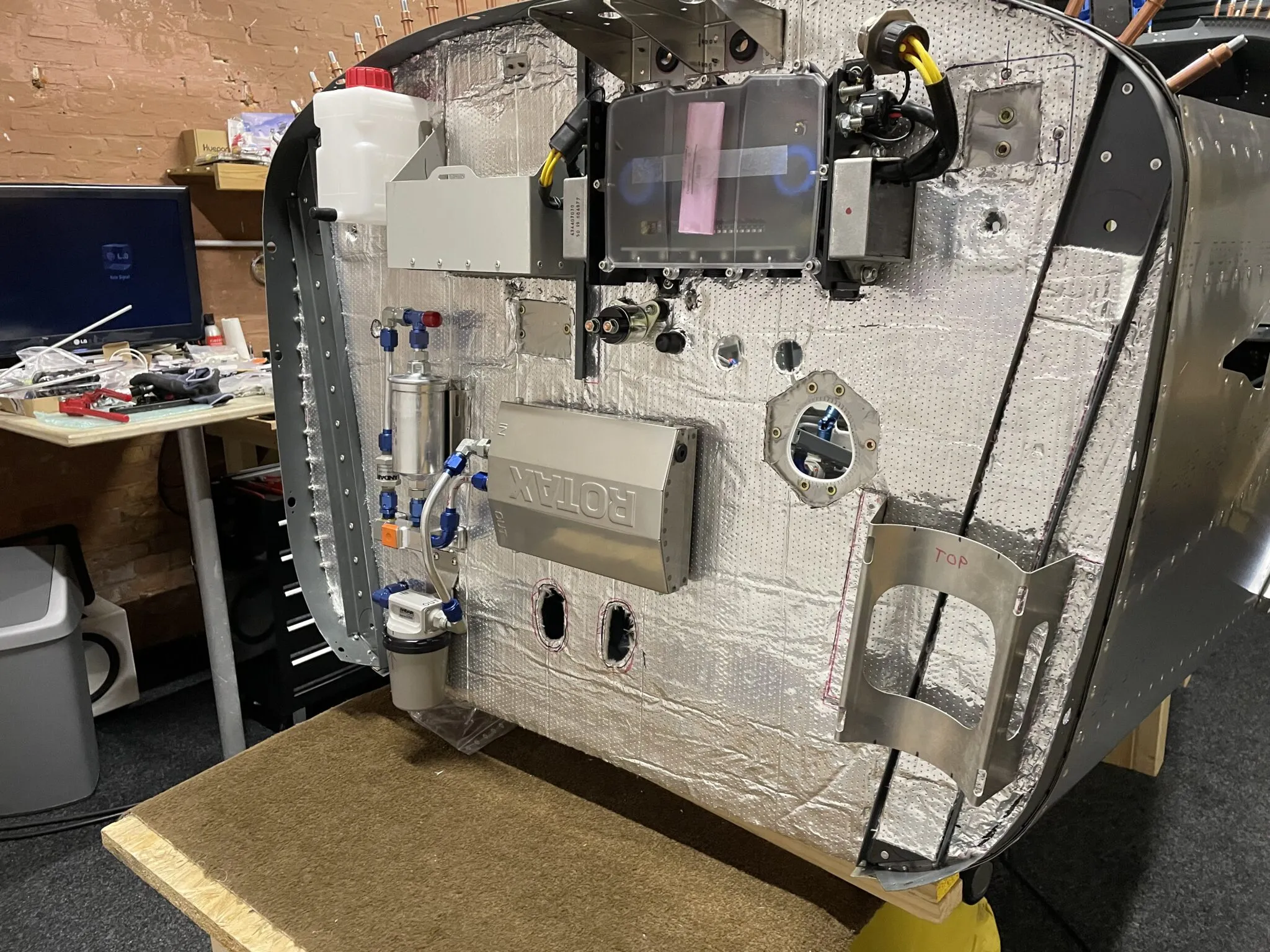
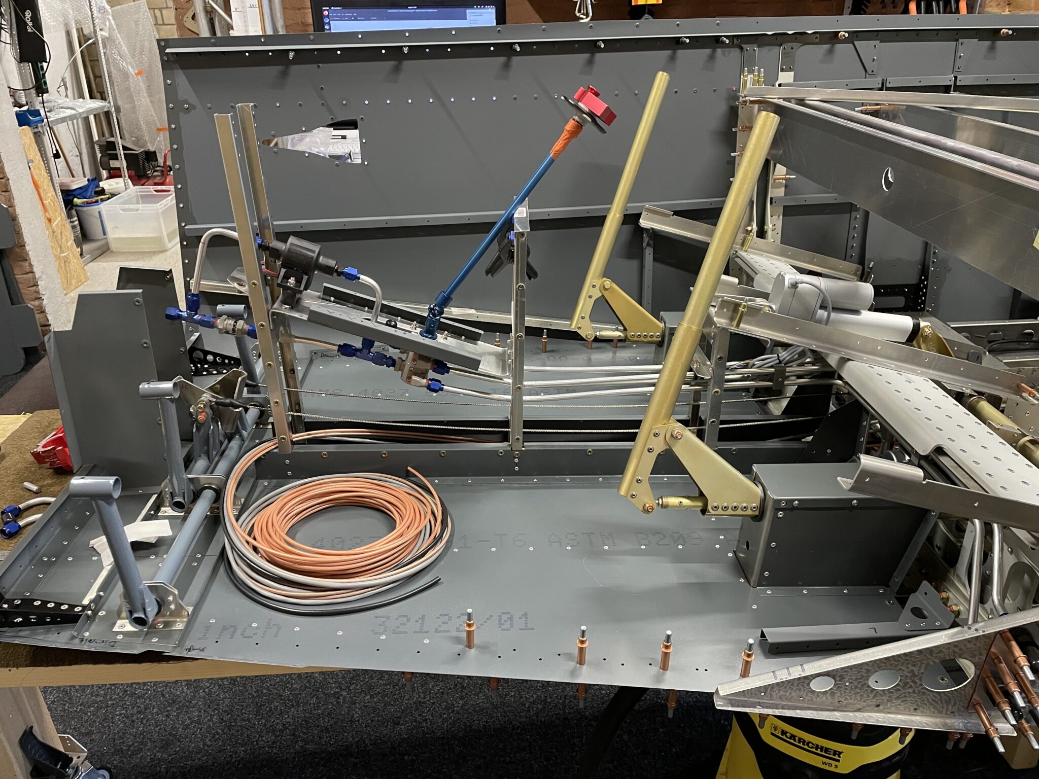
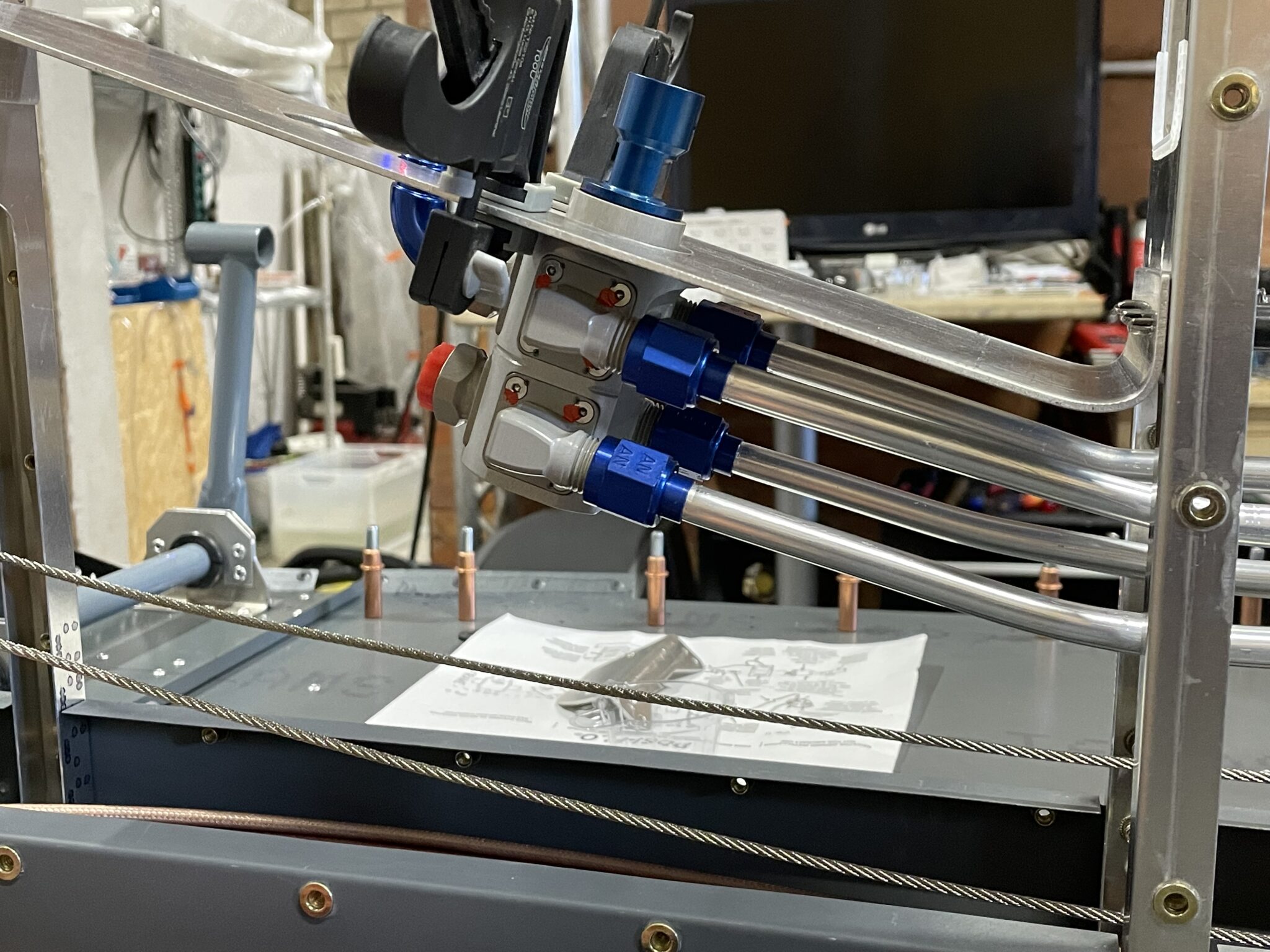
Evan Brunye suggested replacing the supplied jetted T-Piece with a Lockwood fuel manifold, which serves three purposes:
– fuel supply line pressure relief
– fuel pressure sensor port
– simplified fuel line routing.
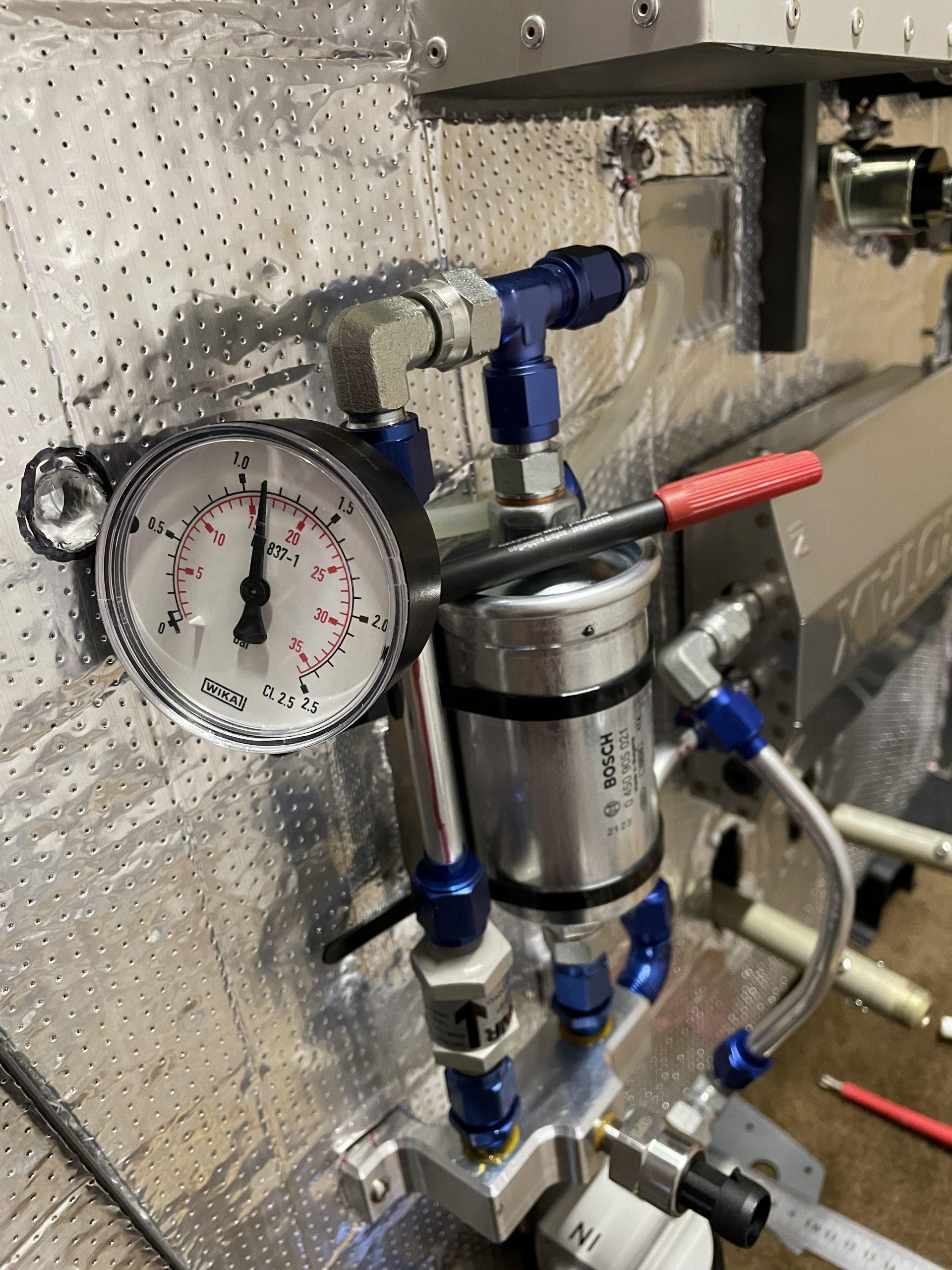
The Lockwood part number is AC-LLC-269iS “Block with restrictor fitting,” which I purchased for $38 in October 2021. Although it’s not listed in their shop, you can still request it. I also followed the recommended orientation for mounting the pressure sensor, with the pressure ports facing down. To avoid the need to change the fuel lines every five years, I installed steel braided PTFE fuel lines, which should require no further maintenance.
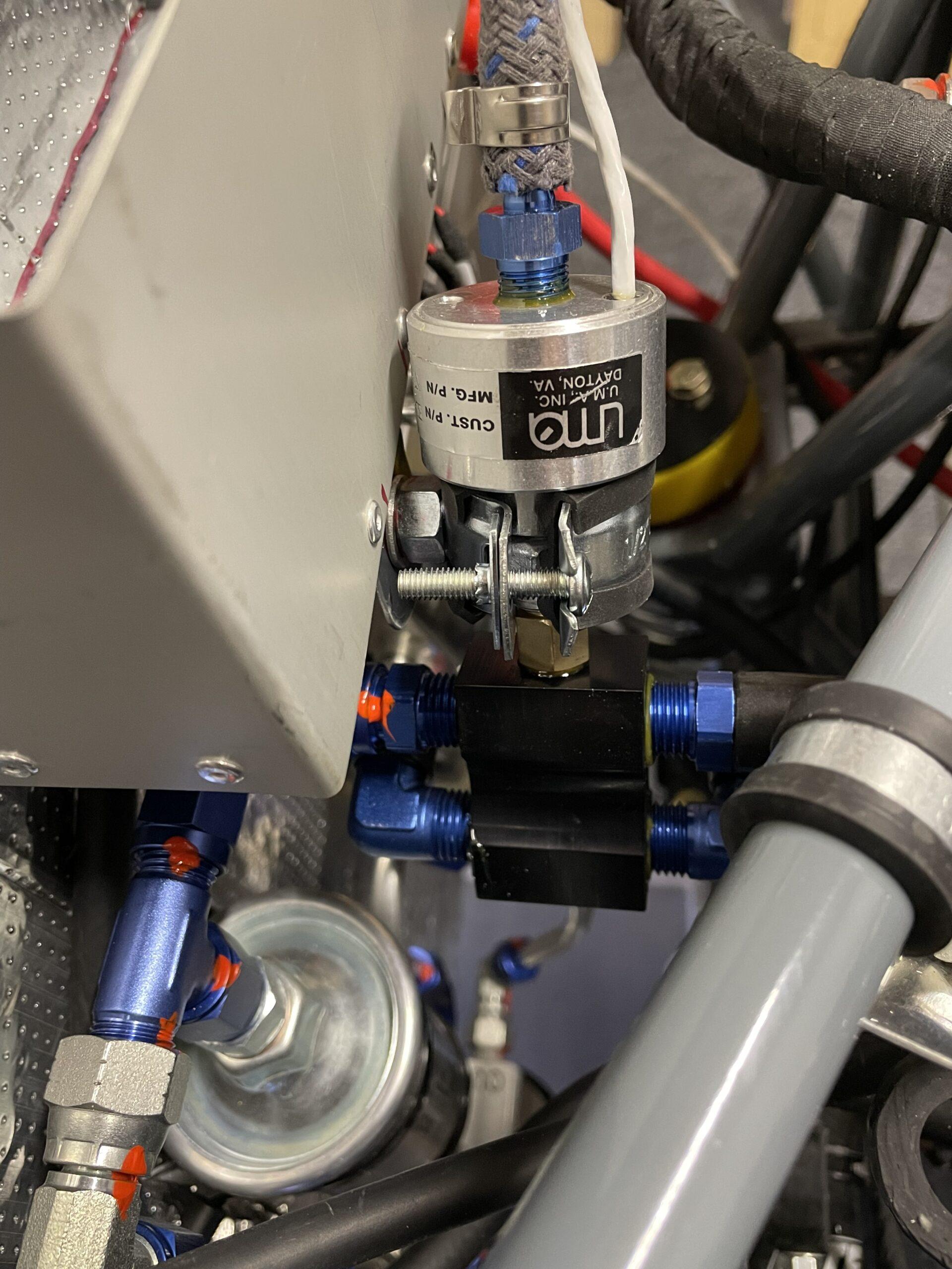
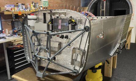
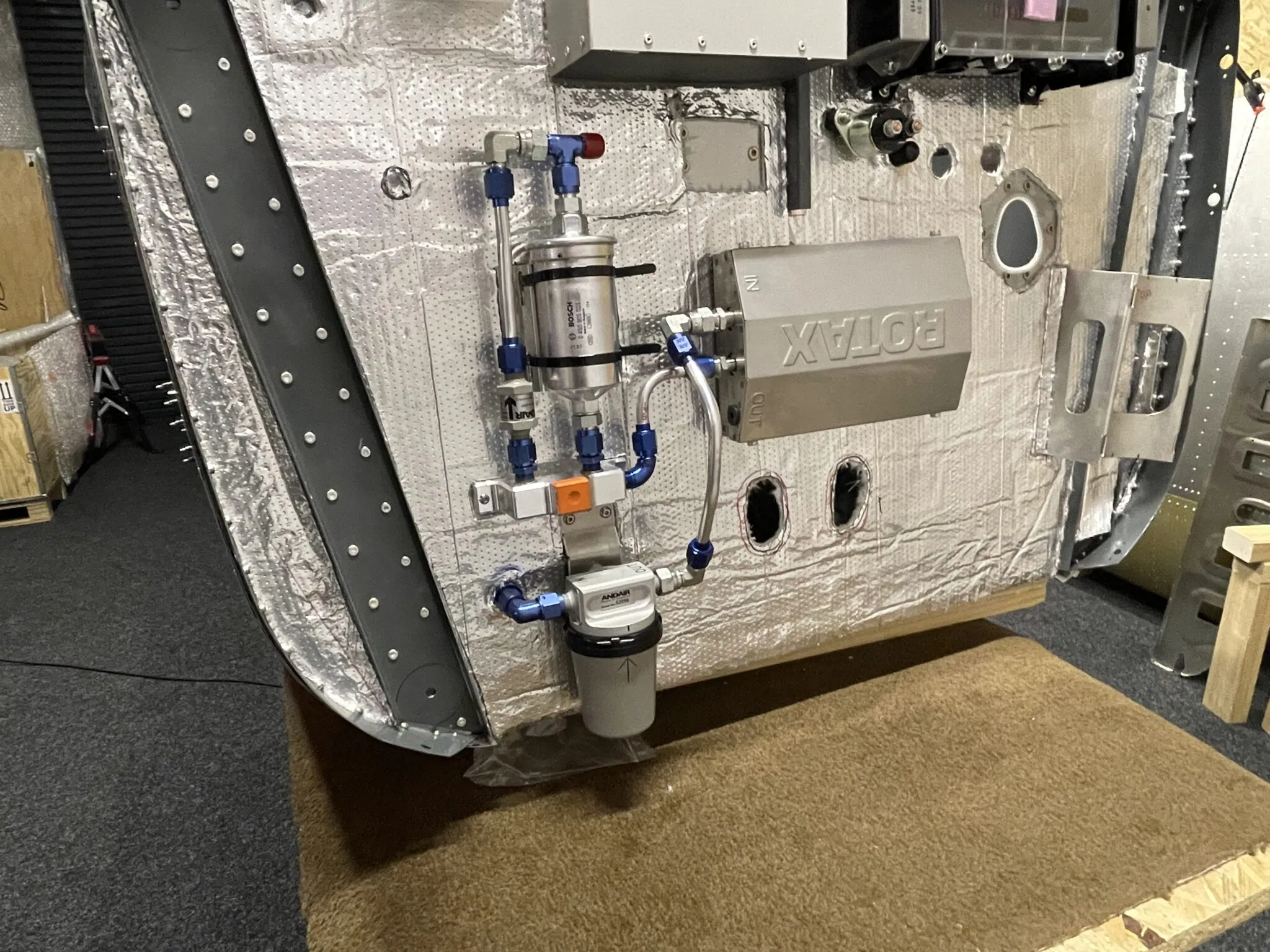
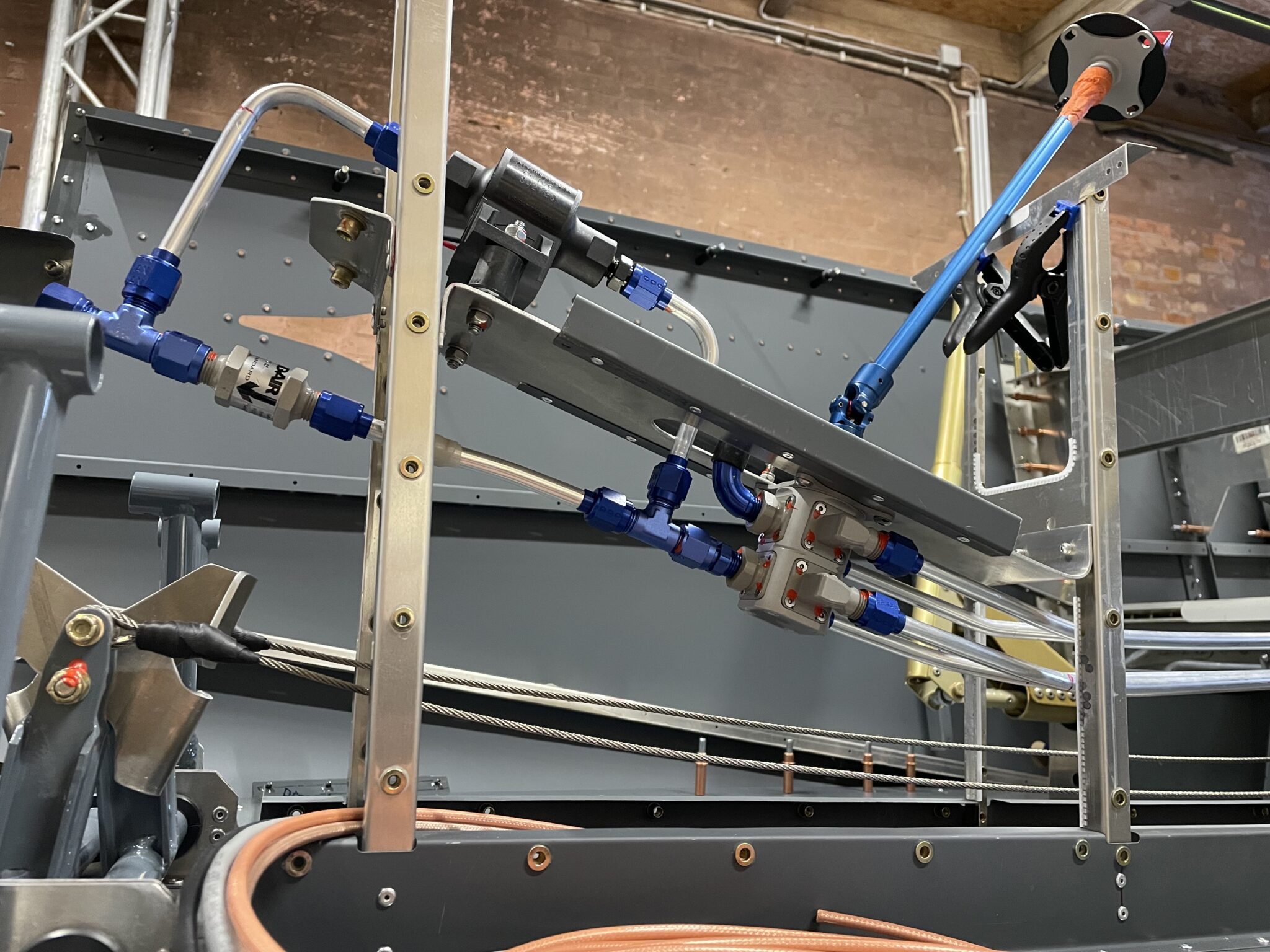
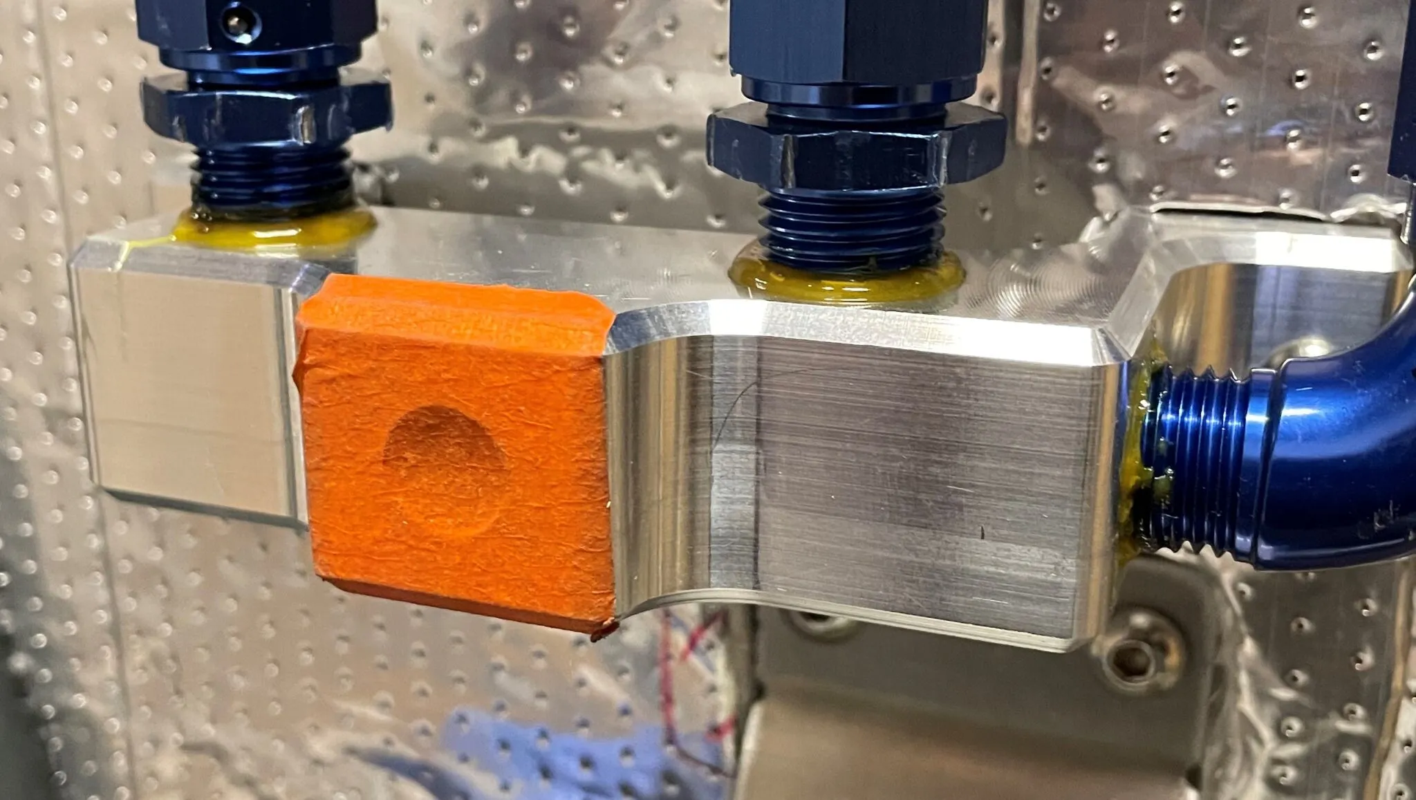
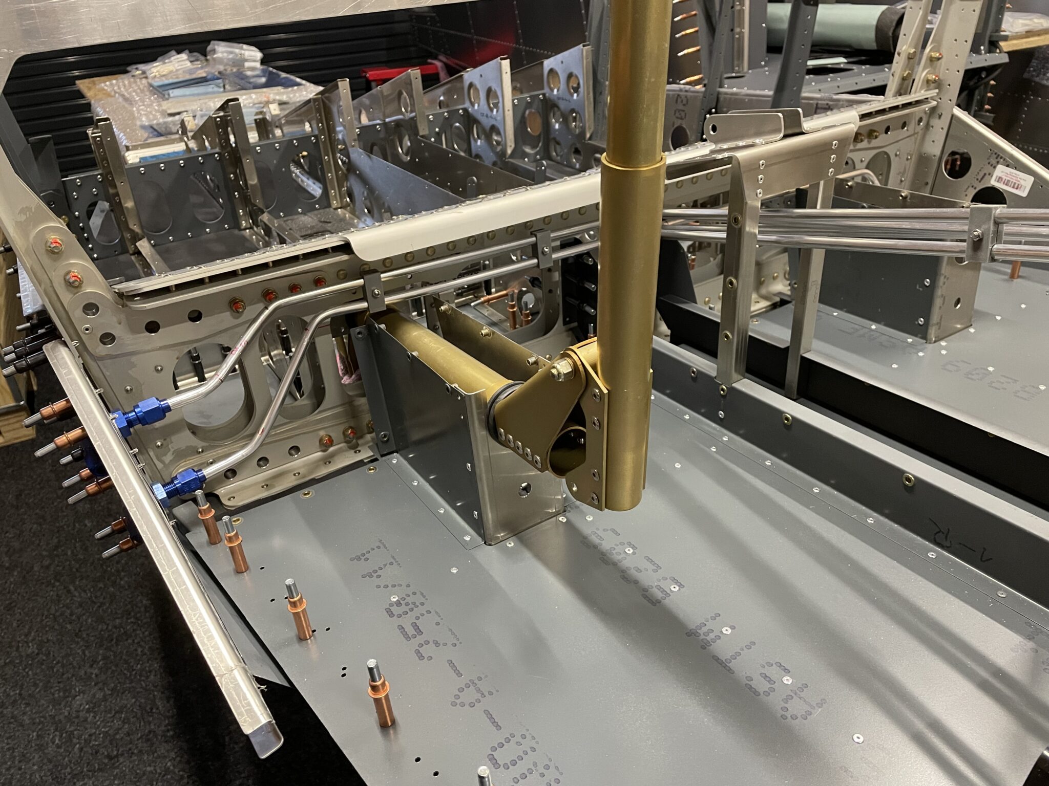
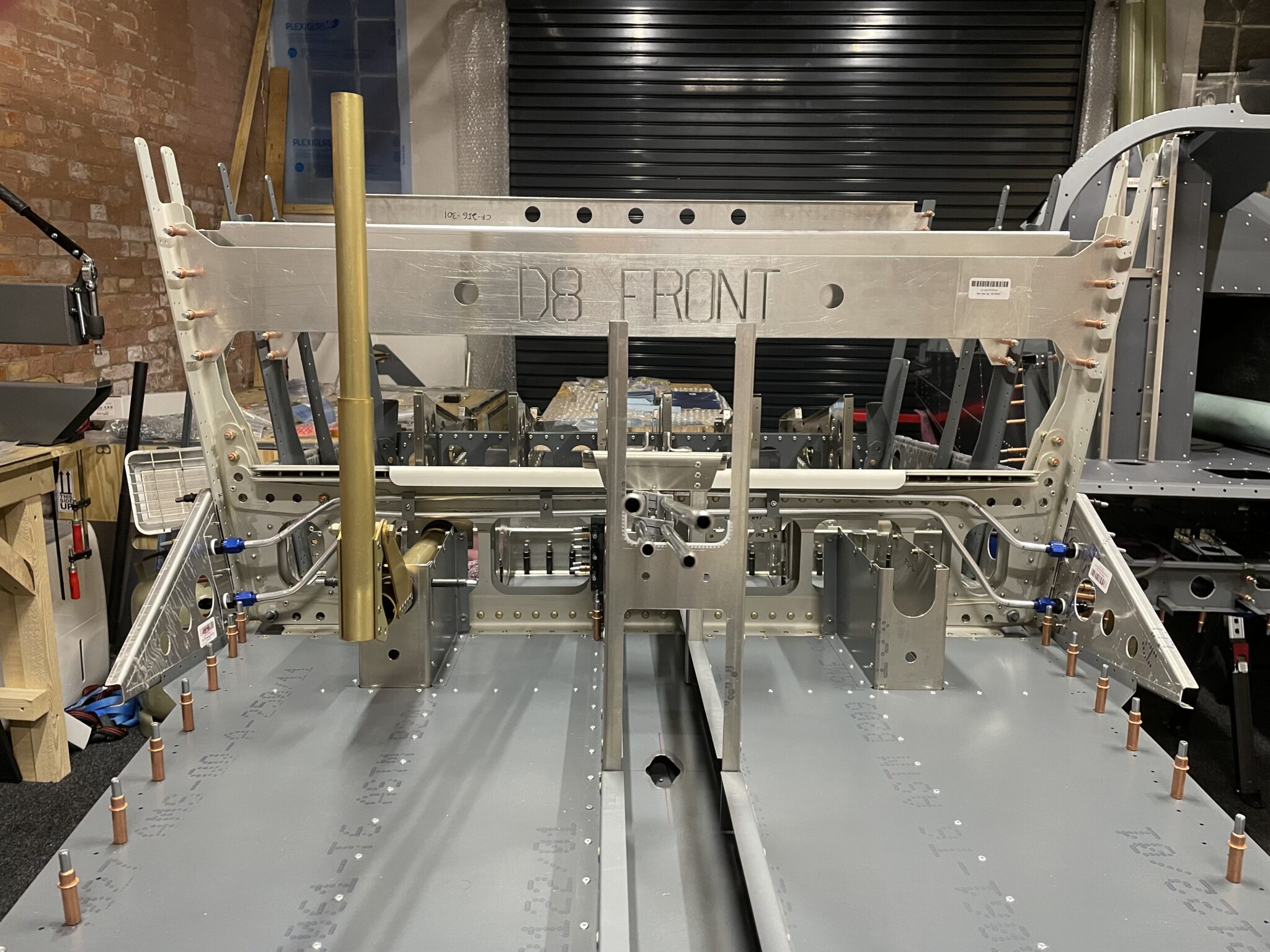
The placement of the fuel system components on the firewall could be improved. I discovered a way to minimize the length of the fuel lines, resulting in a more compact design of the fuel system components mounted on the firewall. The use of a fuel manifold has also helped to reduce the number of fittings, which in turn reduces the possibility of leaks. To prevent the firewall from flexing due to the weight of the aluminum fuel lines, I added a spare bracket to the rear of the firewall.
Pressure test the fuel system as long as it’s easy to access.

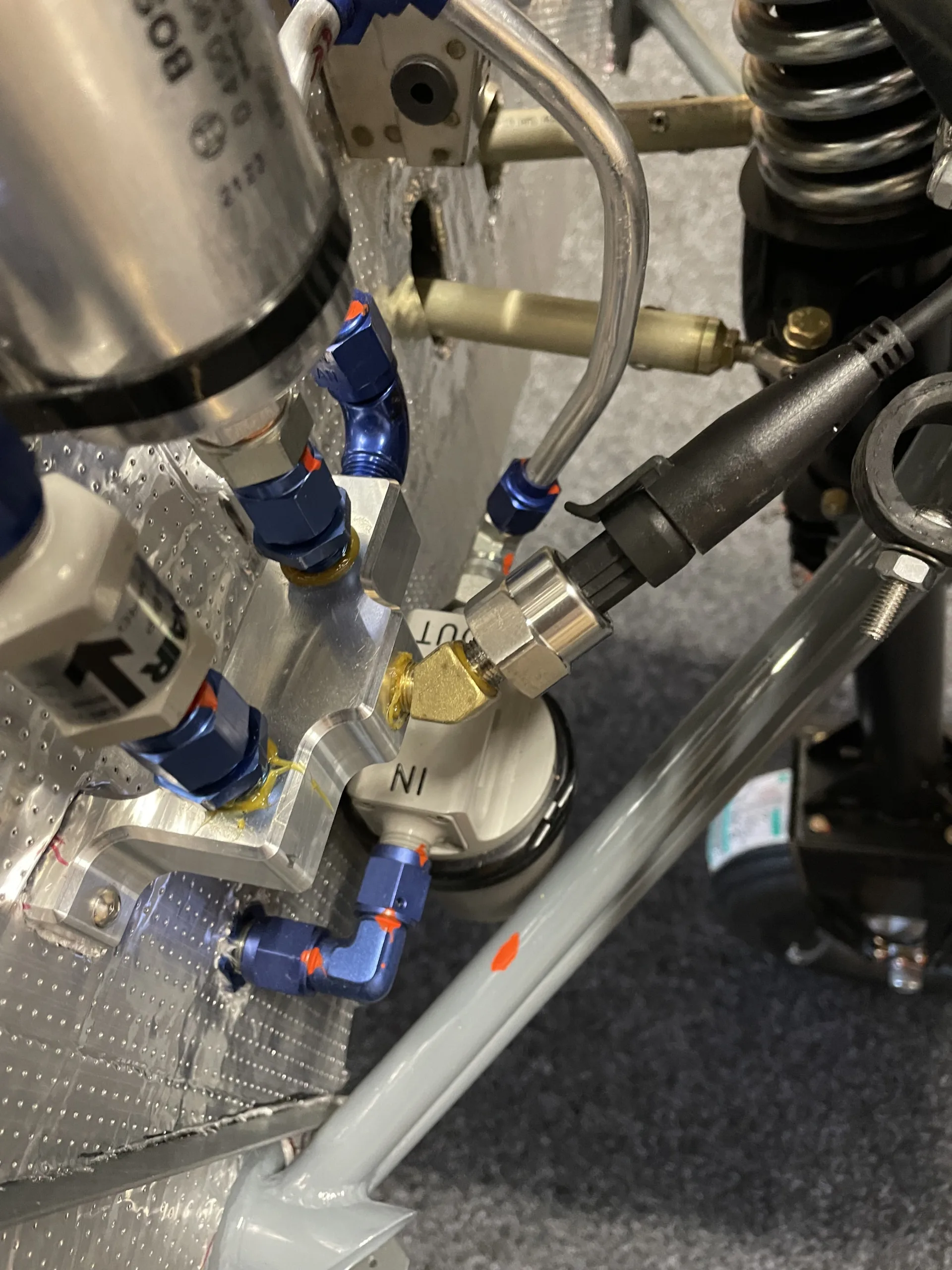
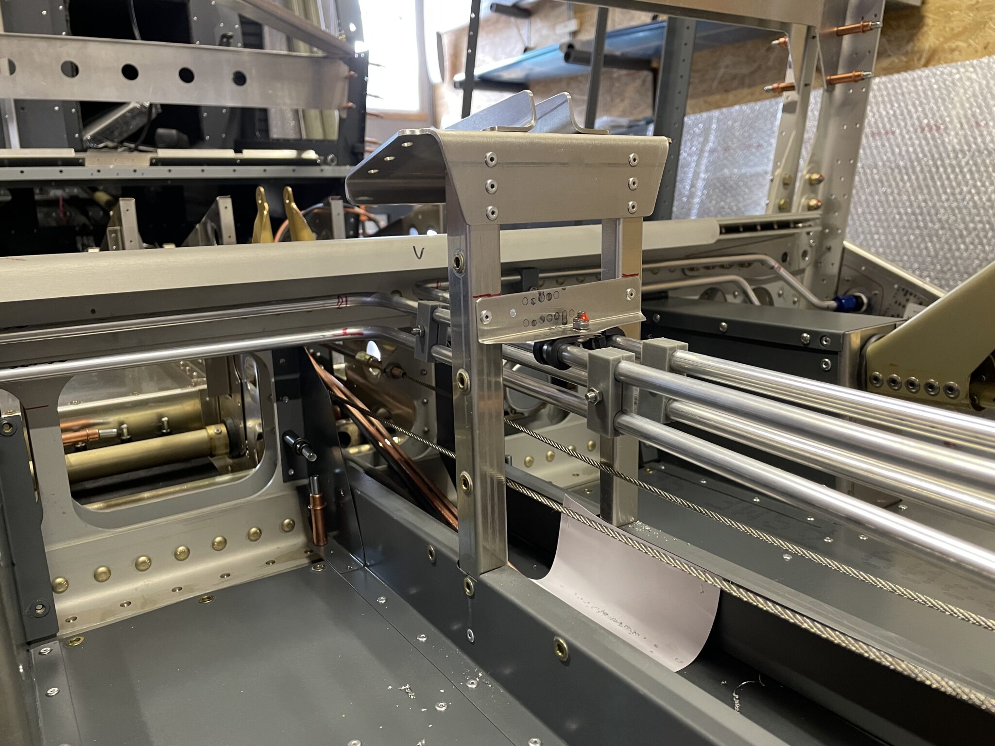
As the boost pump is only used during start and landing, I aimed to keep the normal fuel flow as straight as possible. Following a suggestion from another builder, Evan Brunye, I also kept the fuel lines as low as possible to minimize the risk of fuel pressure issues. When I mount the firewall, I will take care to connect the gascolator without causing the fuel to move up and down the firewall.
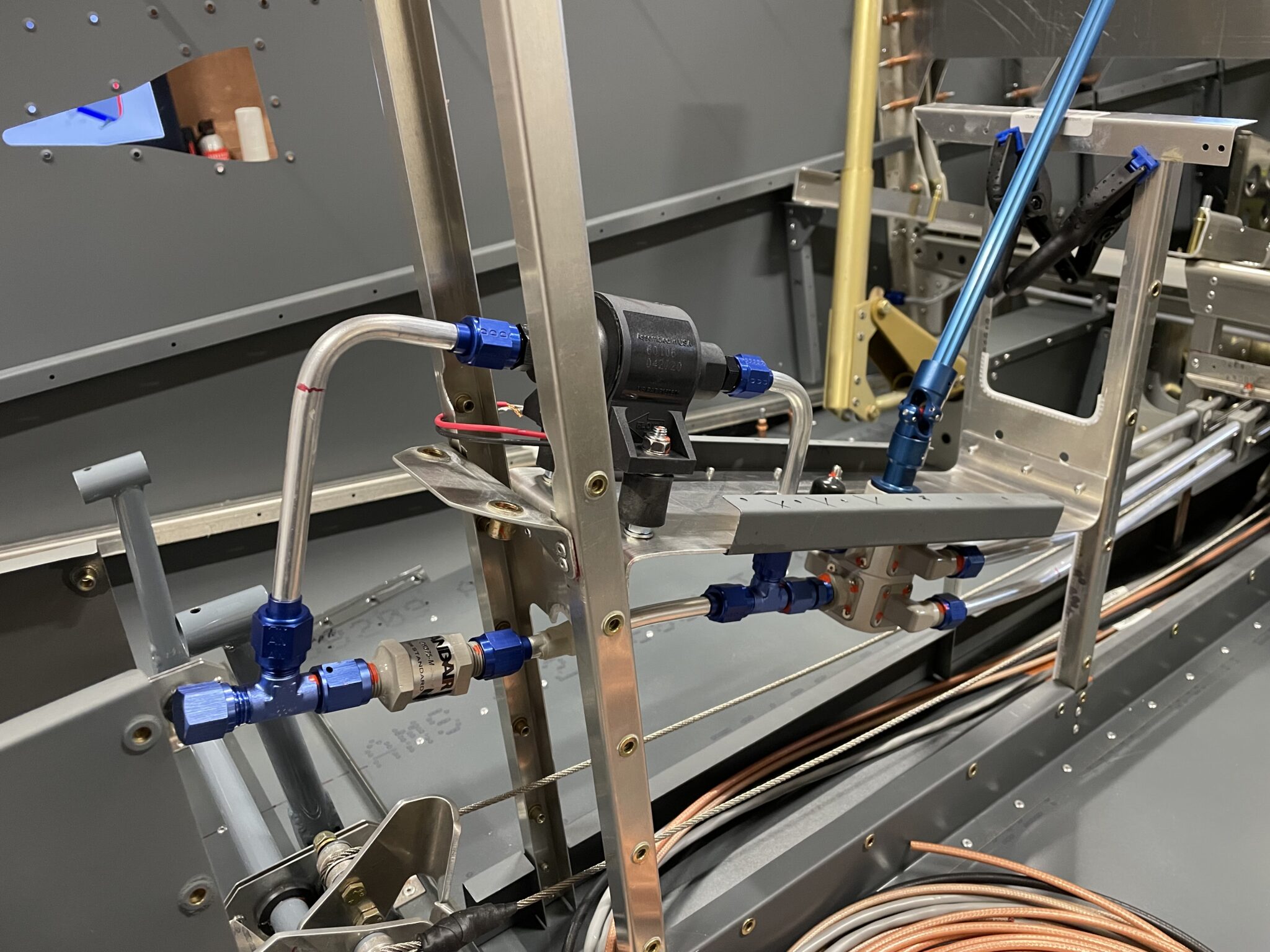
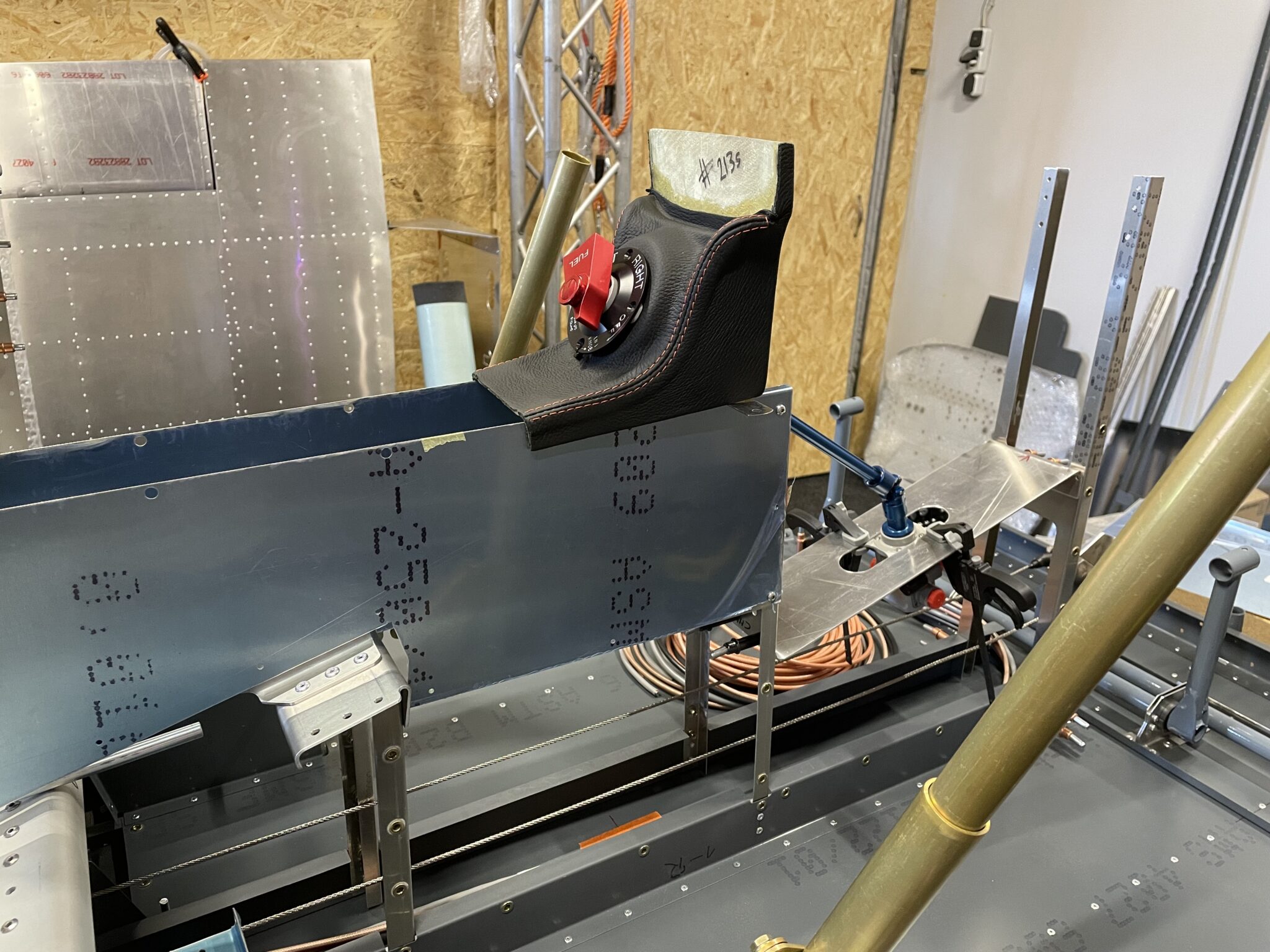
To connect the aluminum fuel lines to the Andair fuel selector valve, I had to change some fittings and other details. Below is a list of the items I ordered from Andair (http://www.andair.co.uk) and other suppliers. Please note that this is an ongoing project, so the numbers and details are subject to change.
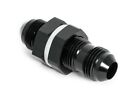
- Andair Check Valve CK375-M (BoP < 1 PSI) with “Male (AN-6,JIC-6)” on both ends.
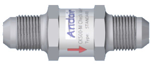
- Andair Check Valve CK375-MM-14-BRP (BoP < 15 PSI) with “Male (AN-6,JIC-6)” on both ends.
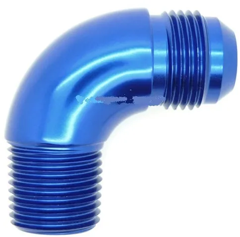
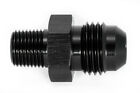
- 4 x 90° Elbow Fitting “Andair EF20”.
- Andair Extension Kit Valve Model FS20-2 with a 12inch extension & 2 Universal Joints:
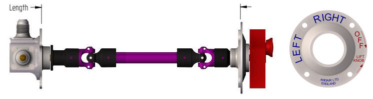
- Andair RA1 Rotary Adaptor (fix fascia plate orientation)
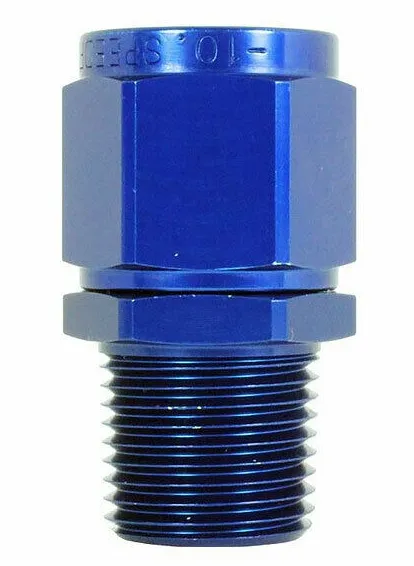
- 2 x full flow 90° 1/4″ NPT to AN6 fittings :
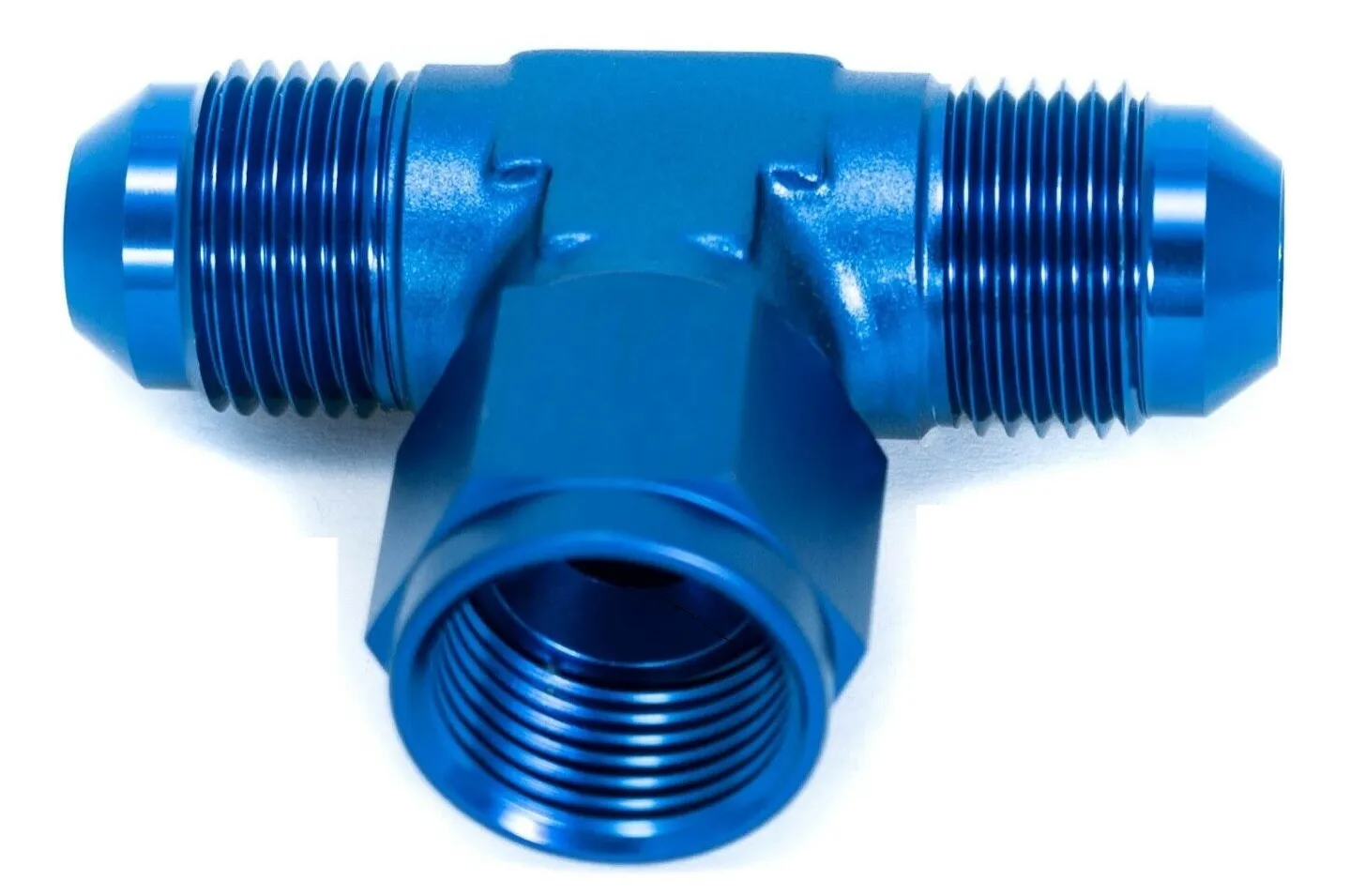
- 2 x AN6 T-Piece behind fuel selector:
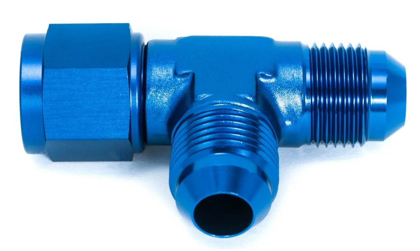
- 1 x AN6 T-Piece on top of the fuel filter:
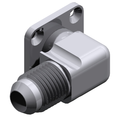
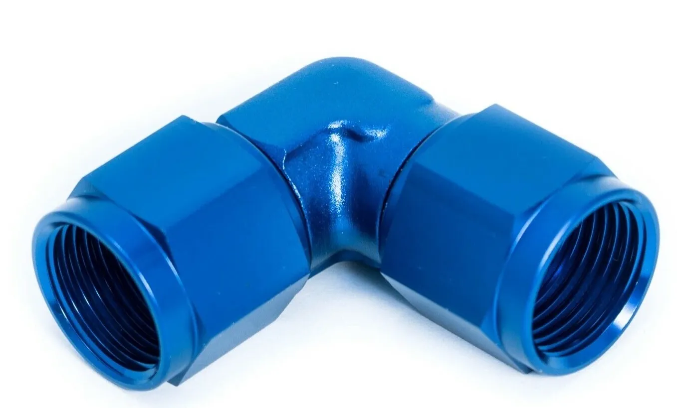
- 1 x AN6 90° female fitting (gascolator firewall):
- 2 x straight 1/4″ NPT to female AN6 fittings :
- 4 x AN-6 Bulkhead Connectors for the fuel tanks:
- 2 x AN-6 to 1/8″ NPT adapter for the booster fuel pump:
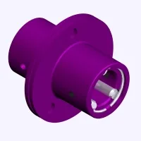
- Fuel Manifold (3 x 1/4″ NPT + 1 x 1/8″ NPT) :
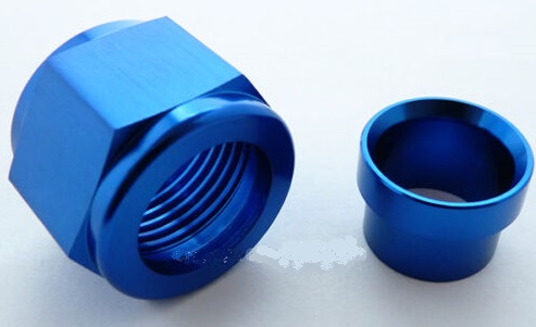
- 22 AN-6 Flare Nuts with sleeves:
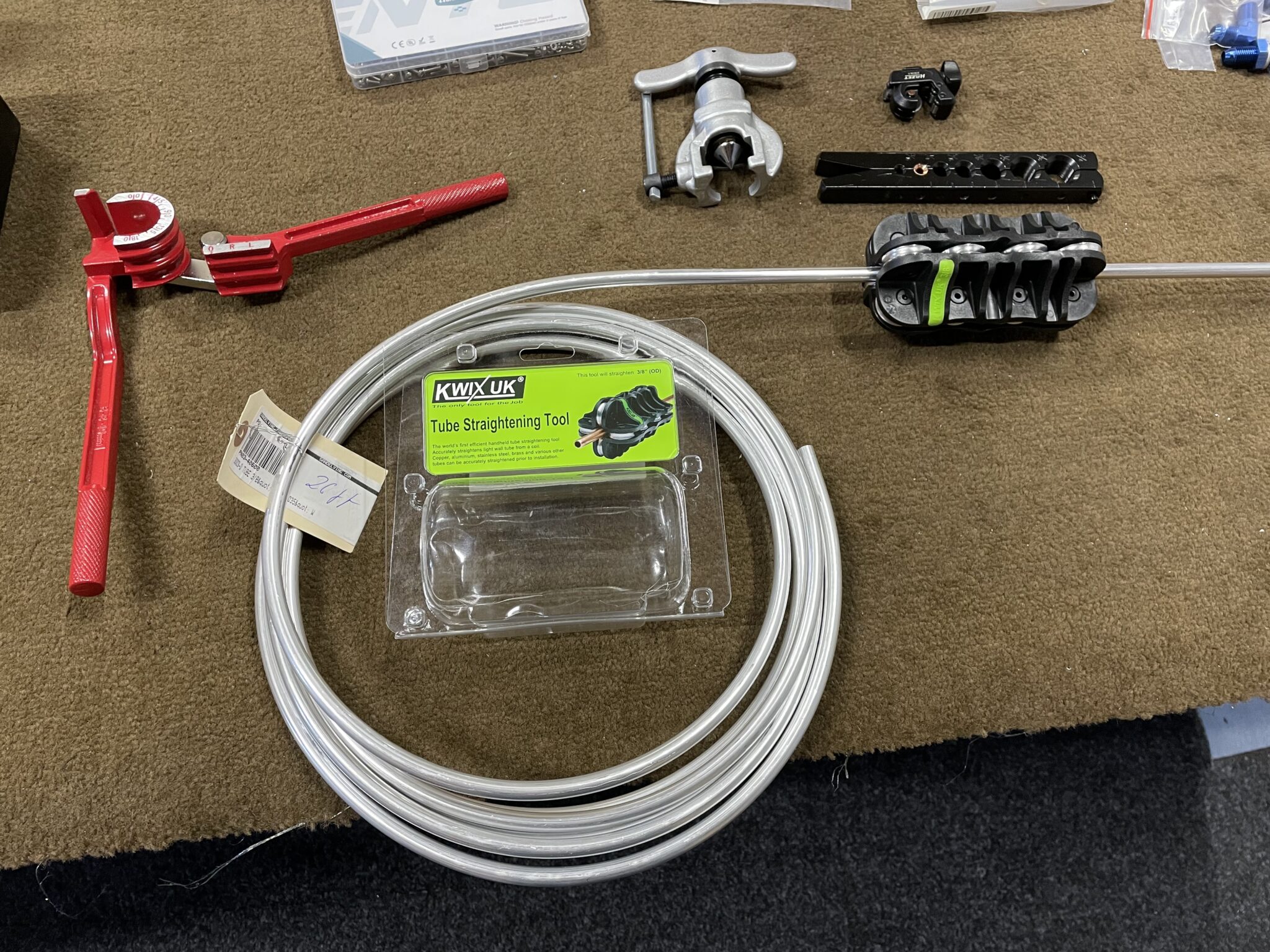
- 30ft 3/8″ 3003-0 Aluminum tubing from Spruce (Versatube)
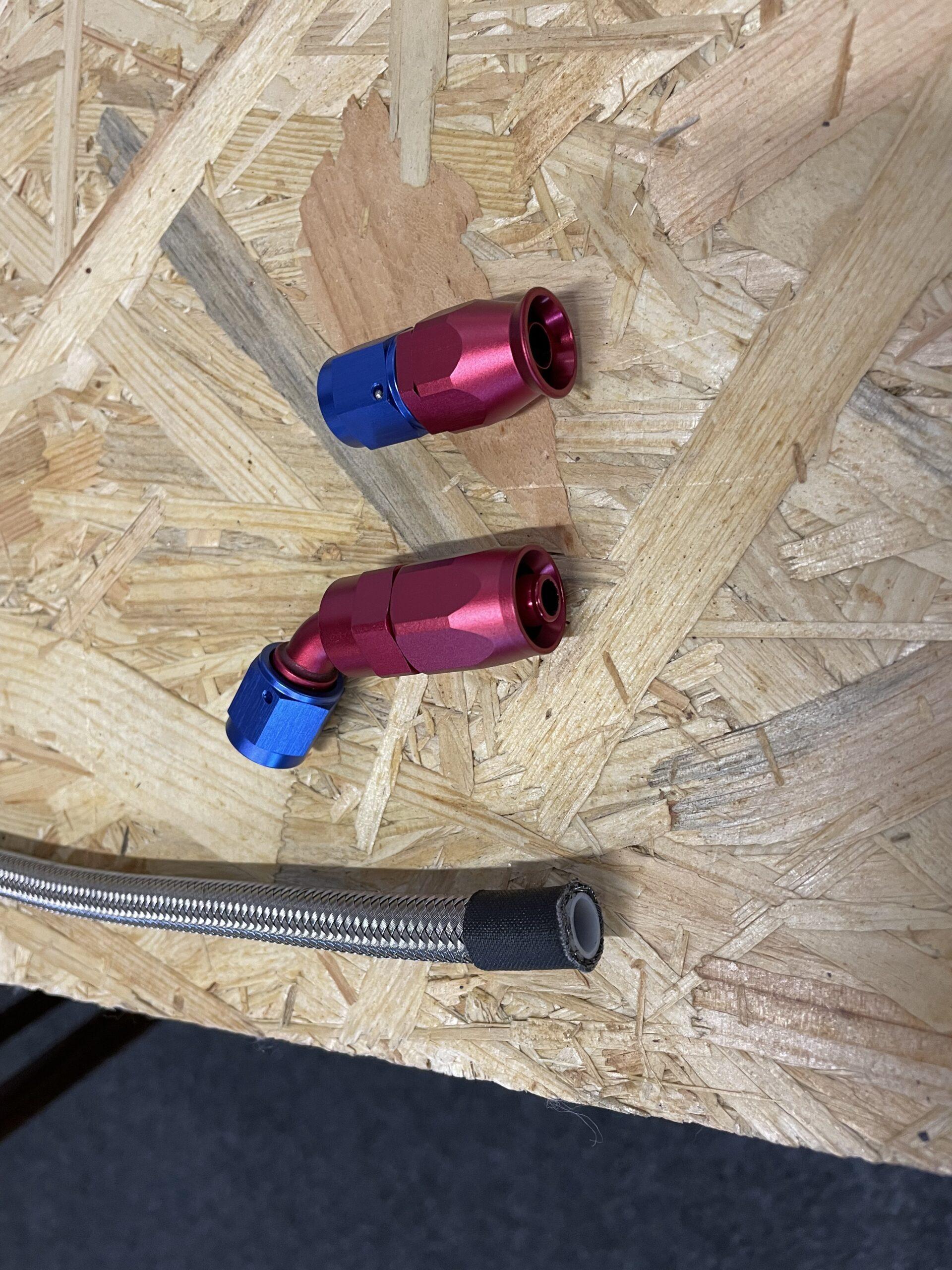
It’s important to note that the flaring tool for the AN6 fittings needs to be 37° and not 45°. Based on my experience, I would recommend avoiding the $20 version of the tool. Additionally, I highly recommend using a “Tube Straightening Tool,” which can make the process much easier. A good tube cutter will also create nice, clean cuts. If you have never done a flared fitting before, there are many helpful videos available online, such as this one: How to Flare Aluminum Tubing for your Experimental Aircraft
I would recomend not to buy the cheepest flaring tool. The one on the picture is like the “RIDGID 41162 377” with the following features:
The RIDGID 41162 Precision Non-Ratcheting Pipe Flaring Tool produces smooth, uniform flares with minimum effort. The pipe flaring tool features a durable eccentrically-mounted, hardened steel flaring cone that produces a rolling action for even metal flow. It produces uniform flare walls without galling. The handle clutch then releases when the flare is complete to iron and smooth the flare. This flare tool displays measurements in both inches and metric sizes. Recommended for flaring aluminum and soft copper, the tool will also flare hard copper, steel, stainless steel and brass through a wall thickness of 0.035 inches. Produces 37-degree SAE flares in 3/16-inch, 1/4-inch, 5/16-inch, 3/8-inch, 1/2-inch, 5/8 and 3/4-inch sizes.
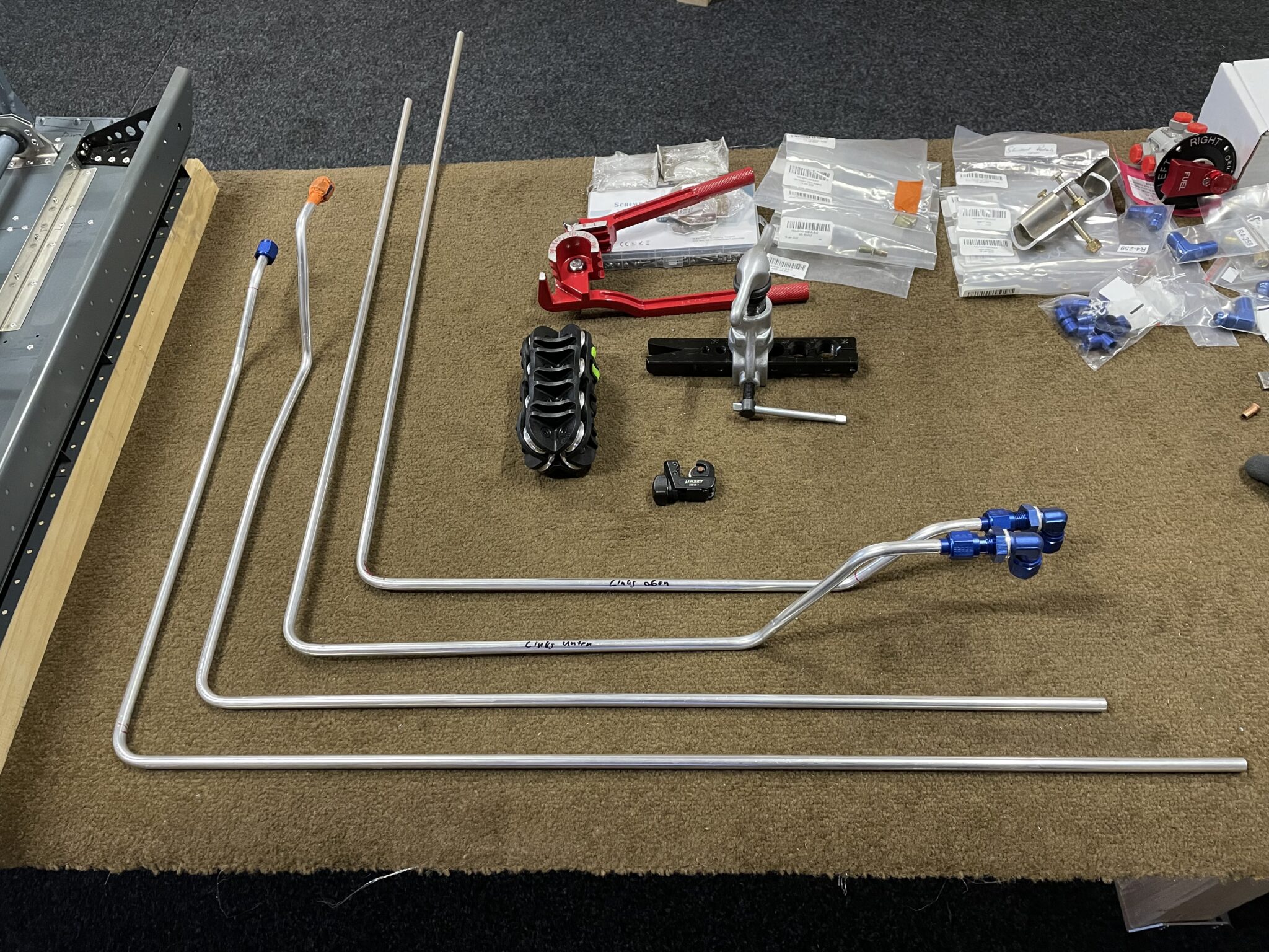
To prevent the fuel lines from touching any metal or moving around, I decided to create some custom fasteners. Using my 3D printer, I made spacers for two 3/8″ fuel lines with a hole for M4 screws. I recommend using PETG or a similarly temperature-resistant material for the print, as it has a melting point of about 260°C. These spacers have worked well for me, and I’m pleased with the results.